
Project planning
How to Calculate Cable Tray Quantities for an Electrical Project
Turn a route drawing into an order list without confusing linear metres, three-metre tray pieces and support quantities.
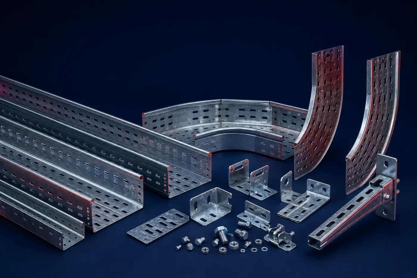
A step-by-step method for calculating cable tray straight lengths, route allowance, fittings, supports and project quantities.
Divide the drawing into measurable routes
Start with a marked-up route drawing. Separate horizontal runs, vertical risers and equipment drops, and record each route by tray width, height and load class. Do not combine routes of different widths into one total because they will become different order lines.
Measure along the actual path rather than the straight distance between rooms. Add the lengths around obstacles and changes in level. Keep the take-off revision with the quotation so later drawing changes can be traced.
- Route ID
- Tray series and width
- Measured linear metres
- Number of direction or level changes
Convert linear metres into three-metre pieces
FRAME integrated perforated cable trays are listed in 3,000 mm lengths. Divide each route's adjusted linear metres by three and round up to a whole piece. For example, a 41-metre route requires at least 14 pieces before any project allowance: 41 ÷ 3 = 13.67.
Apply a controlled allowance for cutting, route changes and site uncertainty. The correct percentage depends on drawing maturity and installation conditions; it should be approved by the estimator rather than hidden inside every line.
Calculate supports and connection hardware separately
Support spacing must follow the engineered load, tray data, cable weight and project requirements. Calculate the number of support points from the approved spacing and include extra supports at changes in direction, risers, equipment entries and concentrated loads where required.
Integrated quick-connection tray designs can reduce separate coupler requirements, but bolts, nuts, covers and fittings still need their own count. Never multiply straight pieces by a generic accessory factor without checking the actual system detail.
- Supports and brackets
- Connection sets
- Covers and cover fixings
- Bends, tees and reducers
- Earthing or bonding items where specified
Finish with weight and delivery planning
After quantity is confirmed, multiply the unit weight by the number of three-metre pieces for each reference. This supports structural checks, handling and freight planning. Width and sheet thickness change unit weight significantly, so use the exact product line.
FRAME lists cable trays by series, width, 40 mm height, sheet thickness and unit weight. Buyers can select the exact references and submit the project list for packing and commercial confirmation.
Frequently asked questions
Quick answers for purchasing teams
How do I convert cable tray metres into pieces?
Divide the adjusted route length by the tray piece length and round up. FRAME integrated trays are listed in 3,000 mm pieces.
Should supports be calculated from the tray piece length?
No. Support spacing follows the engineered loading and installation design, not simply the number of tray pieces.